Showing posts with label AutoCAD. Show all posts

Monday, December 10, 2018

How to Plan Area in AUTOCAD?


This blog is all about AutoCAD which is one of the best drafting software in the world. I’m going to cover the process of plan creation in very simple steps. Preparing a draft of any plan is not an easy task. But when you know the simple and effective steps then this work can become a fascinating and calm work. But before we go ahead and start our discussion on plan creation, I would like to throw some light on an overview of this amazing drafting application. So, Let’s get started.

Few Essential Points About AutoCAD:

  • AutoCAD was developed by Autodesk.
  • It stands for Autodesk’s computer aided design. It’s a drafting and designing software being used worldwide.
  • It works on co-ordinate system.
  • It is used for 2d and 3D design, mostly for civil, mechanical & architecture.
  • It is very popular among small to large scale companies.
  • It makes drawing and drafting very easy and handy work.
  • It is cost effective and highly affordable.
  • Due to its popularity there is a huge demand for skilled AutoCAD employees in the industry. But to be a professional you need to get trained by joining professional AutoCAD course in Delhi from any renowned training institute.

What is a Floor Plan?


Here is your answer:

  • It is a diagram of a building with a top view
  • It consists of measurements, furniture, appliances, or anything else which is essential in the plan.
  • Floor plans help in designing furniture layout, electrical installation, and planning of an area.
  • It also consists of other architectural features like fireplaces, shelves, and benches.
  • Placement of staircases.
  • It has walls, windows, and doors.

Importance of Floor Plan Design

The floor plan is used to communicate your idea in the form of a layout. A good floor plan is a plan that gives a proper flow between spaces to make the movement of a person easy and comfortable.
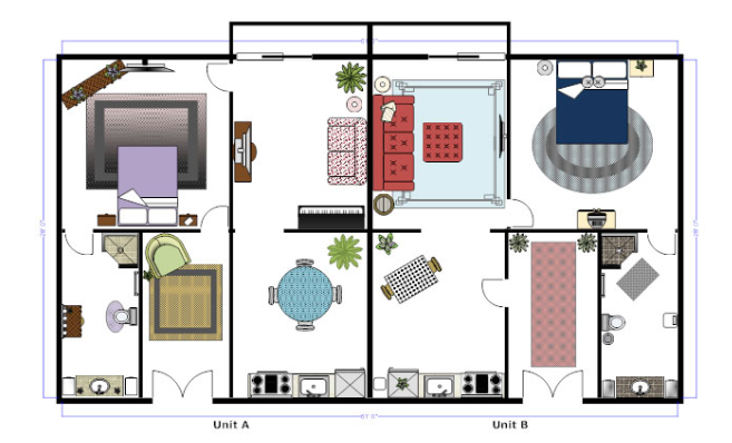
Key Characteristics of a Good Floor Plan When Designing Any House

  • Versatile and flexible: Always make sure in future an office can easily be turned into a child's bedroom whether for your family or a future buyer’s. A room can be used in various ways in future.
  • Size matters: Always think about the number of people using that space at one time, whenever designing any room or hallway.
  • Have efficient circulation and storage.
  • Have natural lighting and good ventilation system according to the sun and wind orientation.
  • Having windows in the plan help in balancing daylight and making room spacious.
  • Maximum use of available spaces is highly recommended.
  • Good and easy circulation of the spaces designed for the client.

How to Draw a Floor Plan?

  • Choose an area: Specify the area to be drawn. Prepare a design based on the size and shape of the location on which to build.
  • Measurements: Do proper dimensioning and measurement of the walls, doors, furniture so that the floor plan will be accurate.
  • Walls: Draw separate walls for each room of the building.
  • Architectural features: Add architectural features like doors, windows, ventilation and other important things like refrigerator, washing machine, dishwasher, WC, wash basin etc.
  • Furniture: Furniture can also be added as per the demand of plan.


How to Plan Area in AutoCAD?

Any drawing is an accumulation of ideas put into written form when we receive them from the customer. Questions come to us in many shapes, like what is the number of rooms in the house? How many people will utilize the dwelling or what is the workflow that will exist in the structure? 
  • First, we prepare a rough sketch according to the need of the client.
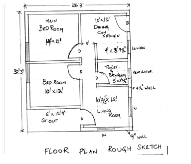


  • Creating a Drawing Using the AutoCAD then, we select our architectural template, Units, Dimension Style, Line scale and other specific variables.
  • After that we create different layers for walls windows, doors and others that are required.


Almost all drawings need to begin with the same approach, so in the floor plan, the perimeter of the proposed house is made first.
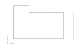


Draw Interior Walls

1.  With the offset command draw internal walls.
2.  Mention offset distance.
3.  Now, you need to select an internal line of the recently drawn wall then click to offset the line option by moving towards the center of the plan. 
4.  Replicate the offset command once again.
5.  Repeat the above steps to mark the offset of the internal wall
6.  Now, join the new lines together, you can take help from the below-given image.
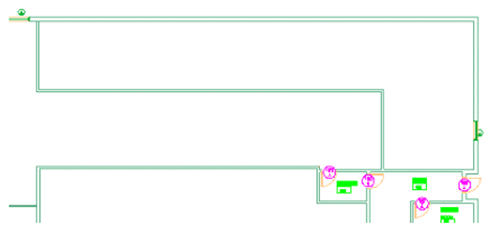


7. With the help of the Trim tool. Trim the extended or excess lines at the intersection of walls to get finished wall placement.


Placement of Doors and Windows

1. Draw using line and arc command according to the width of the door.



2. Repeat the above commands to draw doors with required width.
3. With the help of Trim tool clean up the extra line of doors that are intersecting the walls.


4. With the help of offset tool make Windows by offsetting the walls to the required window width.
5. Trim the extra extended window lines.
6.  At the end, add door and room tags with the help of text command.

So, finally, we have designed a plan in AutoCAD. Wasn’t difficult? Well I don’t think so and I’m sure you too. Now it’s your turn to design a home plan or any other type of plan in this drafting application. I hope you won’t find any trouble while creating, and don’t worry if you’ll find any issue. Just read this blog once again or leave your issue in below given comment area.

Author Introduction: This blog is written by Priya Bhatnagar pursuing ArchitectInterior Premium course from ADMEC which is an education partner of CAD Training Institute 


Monday, October 15, 2018

TOP 10 FREE ONLINE RESOURCES TO LEARN BASIC AUTOCAD


Learning AutoCAD can become easier when you go multiple resources as every resource provides you essential understanding on new aspects. Online learning is also a good option for those who don’t want to go for advanced AutoCAD course training from any training institute.

Here in this blog, I’m going to provide you a list of free online resources with which you can sign up for learning this drafting application at basic level. 

TOP 10 FREE RESOURCES TO LEARN AUTOCAD:


1.CADALYST:

This site offers free AutoCAD tutorials online for every kind of learner therefore new or experienced. Tutorials scheduled in 4 levels: AutoCAD beginner, intermediate, 3D introduction and advanced topics. Sets of sessions are followed by a test to check the performance.  

2.MYCADSITE:

This site offers a wide range of online tutorial series and other cad software tutorials, training and tips.  They also have a video gallery in which they upload the clips of the lessons or the topic clip that teach you how to perform multiple tasks in AutoCAD.

3.TUTORIAL 45:
This is another AutoCAD site to add on your list. Why so? This free resource provides tutorial of AutoCAD with practice lessons, commands list of AutoCAD, 3D projects and many more. This site offers all the basics you will need to learn AutoCAD.

4.CADTUTOR:
You can go for this site enhancing your learning as it provides you better reference resources.

5.ELLEN FINKELSTEIN:
This site is a huge site which offers free AutoCAD techniques, tips and tutorials, that are planned and executed into the sections that makes your research easy to find out the AutoCAD resources. With the number of resources available online, you can easily find the help you need.

6.CAD TUTORIAL BY COMPUTER AIDED DESIGN GUIDE:
Here you will find all the articles related to AutoCAD organized into a list that makes a good free resource you can add to your collection.

7.CADNOTES:
This blog is on cad learning materials. This cadnotes is a blog, featuring AutoCAD series for all types of learners.

8.CADOASIS:
This site is about AutoCAD tutorial, which are specifically designed to introduce cad functions. So, if you’re looking for a good overview about cad so go and check this site out.

9.DRAFTPERSON.NET:
Here you can find free online videos, tutorials and learning documents related to AutoCAD.

10.THE CADSETTER OUT:
Last but not least, this is another online learning platform for AutoCAD learners which offers numerous essential tutorials on this drafting application. You can further find the posts based on the tags which will help you to dive deep into it. 

Conclusion:
So, this is how we have reached towards the end of this blog in which I’ve mentioned top 10 online learning platform for you. I hope all these sites would be helpful for you to polish your learning skills. Now go ahead and join their online learning community.

Author Introduction: I, Pooja Sharma, successfully completed AutoCAD Master course from CAD Training Institute which is an education partner of ADMEC Multimedia Institute.

I hope you will find this blog helpful, do leave comments in the below given comment box.

Wednesday, October 10, 2018

MOST COMMON KEYBOARD SHORTCUTS OF AUTOCAD


For learning anything you need proper planning and understanding. Same rule lies in the AutoCAD course training. You need to understand each concept very well for become an AutoCAD Master. 

Your learning can become easy if you all the shortcuts of AutoCAD, shortcuts means all keyboard shortcuts that mostly used by professionals to save time. 

Most Common AutoCAD Keyboard Shortcuts

Here I am going to tell you the most common keyboard shortcuts that you need to know for becoming an AutoCAD Master. 

KEYBOARD  SHORTCUTS  FUNCATIONS
Ctrl + N
It can be used for open a new drawing tab in AutoCAD.
Ctrl + SIt can be used for save a drawing file in AutoCAD.
Ctrl + Shift + SIt can be used for save a new file as a drawing and in short it is “save as” command.
Ctrl + OIt can be used for clears screen to show the hides palettes and drawing area and tabs. For reset default AutoCAD interface press it again.
Ctrl + 1It is used for open properties palette lists properties of objects. Select the object and press ctrl + 1 for open property palette. The palette also used for modify properties of the object. PR command also used for open properties palette.
Ctrl + SIt is used for open the palette of design center. Design center contains AutoCAD blocks which used directly in drawing.
Ctrl + 9It is toggle command line window. Some reason the command line hidden from drawing area, bring it back by this keyboard shortcut.
Ctrl + CIt is used for copy the object from drawing area. Select the object and press ctrl + c for copy object to clip board
Ctrl + VIt is used for pasted the copied object from drawing keeping original properties.
Ctrl + Shift + VIt is used for the copied object pasted as a block, random set character as name will created thus block. Make block quickly without going the create block by this keyboard shortcut.
Ctrl + ZIt is used for undo the last command and action in drawing. It can be used multiple time for undo multi actions.
Ctrl + YIt is used for redo last undo action which perform.
Ctrl + TabIt is used for cycle all open drawing tabs in AutoCAD.
Ctrl + SIt is used for save the current drawing in AutoCAD.
Ctrl + PIt is used for the current drawing plots.
Ctrl + QIt is used for the quit the current drawing
Ctrl + NIt is used for the create new drawing.
Ctrl + SIt can be used for save a drawing file in AutoCAD.
Ctrl + MIt is used for the repeats the last command.
Ctrl + OIt is used for an existing drawing open.
Ctrl + LIt is used for toggles the Ortho mode.
Ctrl + FIt is used for toggles running of the object
Ctrl + HIt is used for toggles the PICKSTYLE
Ctrl + GIt is used for toggle grip display mode
Ctrl + EIIt is used for through the cycles from the isometric planes.
Ctrl + DIt is It is used for toggles the UCS. It is in AutoCAD only.
F1It is used for call for the help screen
F2It is used for toggle the text screen display.
F3It is used for toggle the object at snap mode
F4It is used for toggles the 3D object snap mode.
F5It is used for toggle the iso plane mode.
F6It is used for toggle the 3D snap to plane mode.
F7It is used for grid mode.
F8It is used for toggles the ortho mode.
F9It is used for toggles the snap mode
F10It is used for toggles the polar mode
F11It is used for toggles the object track mode
F12It is used for toggles the dynamic input mode.

By using these shortcuts one can easily execute their work without spending much more time on it. These keys are very useful for doing your work properly and quickly. 

About Author:  Hi, my name is Priyanjali, I have completed my AutoCAD Master course from CAD Training Institute which is an education partner of ADMEC Multimedia Institute. This blog is one of the parts of my AutoCAD project issued by my faculty Mr. Kapil Sir. I hope the above-mentioned keys would be helpful for you.                                                                                                

Wednesday, October 3, 2018

How Learning AutoCAD 2d and 3d is Beneficial For Mechanical Engineer (Designer)


AUTOCAD is basic software which is used for 2D and 3D modeling design, usually it is for civil, mechanical and architecture domain and this software is very popular among small to large scale companies. Before going for learning advanced AutoCAD course in Delhi, you need to understand why you are learning AutoCAD and how it is beneficial for you? In this blog we are going to cover the solution of these questions.

Well yes, this drafting application is very helpful for mechanical engineers as we all know Mechanical engineering is a broad field that encompasses industry, business, medicine and even law. Planning and designing mechanical objects is the primary focus of mechanical engineers, whether they are producing engine and motor components or complete devices like refrigerators and robots. Design programs like AutoCAD usually help mechanical engineers to do their jobs with ease and with quite good efficiency, saving time and resources.

AutoCAD is known as a 2d and 3d dimensional application which is mostly used by professional mechanical designers, architects, civil engineers etc. 

Below I’m giving you some solid reasons that will provide solution of your question “How Learning AutoCAD 2d and 3d is Beneficial For Mechanical Engineer”

Reasons to Learn AutoCAD 2d and 3d for a Mechanical Engineer

  • Prevailing Features
It comprises of a powerful collection of features that assist one to create desired output.
  • Design & Analysis
It allows us to design and analysis where design stands for the production of models, and components. The design is needed to produce models and prepare component production whereas analysis is used for measuring purposes such as to check the influence of elements. 
  • Complications Eliminator
As per the survey of General Electric, that using AutoCAD one can get rid of the problems and errors related to drafting projects. 

So, for mechanical engineering student it’s better to have knowledge of CAD basics before getting into any software, manufacturing and design company or industry.
  • A Complete Pack
There are many applications in mechanical engineering - designing parts and assemblies, arranging equipment in a plant, creating renderings and animations of machines, analyzing stress and fluid flow and much more which can be easily achieved or done by AUTOCAD software with less or zero error. 
  • Long Established Application
AutoCAD is an old and long-established CAD application, and probably has the most existing drawing files of any. 
  • Flexible
It’s very flexible and used in lots of different ways, not just in mechanical designing but in other fields too such as civil engineering and architectural designing. 
  • A Versatile Application
In mechanical engineering, designing parts and assemblies is usually done in 3D CAD modeling software. It can work well in 2D as well as in 3D. So, it’s a highly versatile and powerful application that works proficiently in both 2D and 3D. 
  • AutoCAD is for All
It is mainly known as an application for designing and drafting. So Mechanical designers who are working in the field where designing is required should know AutoCAD. Apart from mechanical designers it is used by professional architects, interior designer, civil engineers and by many research scholars too for different purposes. 

In more easy terms we can say ATOCAD provides us very good platform to complete our task with ease. 

Some of other features of AutoCAD are as follow: 

  • It is simple to learn, easy to operate, commands and tools are made perfectly for learning process and as well it will clear all your basics. 
  • It gives us a platform and way to communicate and refine design ideas.
  • It is also incredibly important for manufacturing. 
So, this is how we have reached at the conclusion of this blog. Nowadays nothing can be manufactured without a CAD model since nearly all large-scale manufacturing systems are based on CAD models. And moreover, almost every mechanical and core company uses this software. So even if you don't go into designing department it is a must as at one point or the other we will be using it in your job. 

And As a mechanical engineer we should have good explore in designing filed which can be achieved by AUTOCAD!!

Author Introduction: 

This blog is written by one of the brilliant students Rishabh Dev Sinha who is pursuing AutoCAD Master course from our training institute. 

Author Reviews on AutoCAD: 

SO, in my view, it is one of the simplest software we should learn especially for MECHANICALS as we have to work in manufacturing and designing fields.

So, we can say for mechanical engineers “AutoCAD is the base of all designing software and we must to do it”!!!!

Hope, this blog will help you understand the importance of AutoCAD. If you are interested in attaining AutoCAD training in Delhi then you can go to CAD Training Institute which is one of the professional AutoCAD training institutes in Rohini, Delhi.

Check out our all CAD Courses to know more.

Tuesday, September 4, 2018

USE OF VISUAL STYLES IN AUTOCAD


AutoCAD introduced a feature known as Visual styles in AutoCAD 2007. The main purpose of Visual styles was to give the user control on how objects lock to whole new level. You can control how edges face look, as well as background, shadows, materials, and lights all without rendering the drawing. It gives the user the freedom that other drawing software don’t. By controlling the overall look of the drawing through visual styles it helps to provide an immersive experience to the user. This feature makes the learning of advanced AutoCAD course easier for me.


WHAT ARE VISUAL STYLES IN AUTOCAD?


VISUAL STYLES help the user control the edges lighting and shading. Visual styles are useful when you want to create a rendered looking drawing that can still editable. It also helps you to draw drawing more clearly. When you open any drawing the default visual style is 2d wireframe. AutoCAD 2011 introduced several additional visual styles. The user now can control the style of visual style by changing its properties.

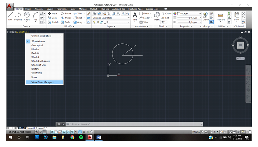
The visual styles manager displays all the styles available in the visual styles tab. The setting for the selected 
the style is displayed in the panel below the thumbnails.


TYPES OF AVAILABLE VISUAL STYLES


2D Wireframe. This visual style displays an object with lines and curves that represent boundaries.

Conceptual. Display object using some shading to make them look smooth. This visual style uses shades of warm and cold colors. The effect not that much really, but it makes the details of the drawing clearer.
  • Hidden. Display object using lines.
  • Realistic. Display object using shades and material almost makes it look realistic.
  • X-ray. Display objects with transparency like x-ray vision.

*There are more but these are the one I use more often.

CREATING VISUAL STYLES

  • Create a layer choose any color you want.
  • Create a model.
  • Click the view tab, then click visual styles manager.


  • Right, click the conceptual swatch copy then again Right-click anywhere in the swatch area again and choose paste.


  • Right-click once again to edit name and description. Name your visual style and enter a description.


  • Go down to the edge settings section. Set the show value until it feels right.
  • Change the silhouette edges setting.
  • In the edge settings section and select the overhanging edges and jitter edges button to turn on these features.
  • Select the model.
  • From the view, tab choose your visual style
  • And it’s done.

BENEFITS OF VISUAL STYLES IN AUTOCAD


Visual styles in AutoCAD helps the user in many ways, firstly it gives more freedom to the user on how he wants to see the creation he created in many styles from 2d wireframe to realistic. When the user wants to see his drawing boundaries he can switch to 2d wireframe and when he wants to see the drawing in a real manner he can switch up to reality. There are ten default styles in AutoCAD that helps the user to create without much hassle.

From AutoCAD 2007 where they were first introduced to now, visual styles have given his assistance to the user so they can create their desire in form of a drawing. 

Thanks to all these features, my experience of learning AutoCAD course from CTI which an education partner of ADMEC Multimedia Institute has been amazing. You can even create your own visual style the process is given upward you can choose your style how you would view the drawing. Its user-friendly interface helps the user to change its setting anytime whenever he wishes to. You can even change the lighting quality which helps in creating realistic shadows and give a nicer appeal to the drawing. Through 2d wireframe, the user can adjust the boundaries. Lastly, my overall experience with visual styles in AutoCAD was great with the help of these features I was able to create some good drawing.
Visit BlogAdda.com to discover Indian blogs

Monday, August 20, 2018

Importance of AutoCAD for a Mechanical Engineer


Mechanical engineering is a very extensive sphere of operation which has applications over in many other industries and fields of work. Mechanical engineering involves the formulation and design process of many articles that could be of interest to the respective fields. So, in this blog, I’m going to discuss some essential points or advantages which you can attain after learning AutoCAD course from any renowned training institute or any other resource.


How AutoCAD Helps a Mechanical Designer?

  • AutoCAD is one such design program that helps the mechanical designers in several ways. One of the essential are as follow:
  • AutoCAD achieves the desired goal of Mechanical designers by creating blueprints and first drafts of designs.
  • This helps them to not only refine their design before it makes its way to production but also saves many resources in the process.
  • AutoCAD helps mechanical engineers to start putting down their ideas in detail which makes the first draft of their components much more detailed than they usually would have been. After detailing their ideas, they can then get down to analysis to perfect their design to save resources and get the best possible iteration of an object that they can. 
  • Not just that, but AutoCAD can also be used to correct errors made in betas of existing machine equipment so it can act as a correction software as well for the design that is input, making it extremely versatile. It eliminates the need for traditional prototyping which involves a lot of time as well as reserves.
  • The first function of AutoCAD that can be stated is the reduced cost of the design process. By getting rid of the requirement of physical materials and man hours to build prototypes, AutoCAD makes it a lot easier for individual companies or startups with very little capital to also build extremely complex and sophisticated mechanical drawings without putting any investment in. 
  • Also, the simulation process that can be accessed in AutoCAD can help engineers test if their component actually works the way it was intended to. Even extremely large models can be scaled down in this digital software for beta testing this way.
  • Another advantage of using AutoCAD as a Mech engineer is that quality tests can be run whereby simulations of extreme strains can be applied on the machine operation to test the limit till which the machine can be run. 
  • This would be virtually impossible to test in real life without investing a lot of time and assets which would eventually even result in the loss of the prototype machinery. 
  • Also, all this is done in extremely fine detail, so it is an extremely viable and close indicator of what is most likely to happen physically. Hence when working on projects, engineers can be assured of their designs and if they’re applicable in the real world.
  • Also, AutoCAD helps in cutting down the time taken by engineers working on projects so they can meet deadlines of projects faster than they would have in the past. 
  • Designing a marketable product is very competitive where the sooner your product is ready to go on the market, the more is going to be the profit. 
  • This software enables engineers to conduct very thorough testing in a very little amount of time. 
  • Also, if needed to be revisited and altered, the design doesn’t take that much time to be tweaked on AutoCAD whereas, with traditional designing processes, it would take a lot more time to go back and start all over again with twice the material usage and a lot of wastage of energy.
  • AutoCAD allows mechanical engineers to consult with different departments of the company for design input and to meet design requirements digitally which again saves a lot of time. They can then ensure that the design meets all the regulations that are imposed by their employers without having to physically demo their project and then if needed, go back to the drawing board. This way makes it a lot easier for everyone to collaborate with the engineers conveniently and efficiently.
Finally, AutoCAD has practically revolutionized the field of mechanical engineering by changing the way we think about the whole design process. Also, by making leaps and bounds in progress with prototyping, troubleshooting, and quality testing it has had a huge impact on saving supplies and materials but most importantly, time of both the people working and whom they are working for. AutoCAD is the most commonly used drafting tool by mechanical engineers, and for good reason as well, as is now evident.

Thus, we can consider AutoCAD as one of the most essentials application to learn for a mechanical designer. ADMEC Multimedia Institute is offering professional training of AutoCAD under the guidance of expert trainers who cover significant aspects of this drafting application. So, go ahead and join the AutoCAD Master course which covers both 2d and 3d parts of AutoCAD. 
I would be glad if you will share your views on this blog in the below-given comment area. 

Tuesday, July 24, 2018

HOW TO CREATE AN ISOMETRIC DRAWING IN AUTOCAD


If we talk about the isometric drawing in AutoCAD then these drawing aren’t 3d drawing. We can’t compare them with 3d. If you want to learn advanced AutoCAD then comprehending the concepts of isometric drawing is really significant.

In this article, I will explain the methods of creating an isometric drawing in AutoCAD. So, let’s start from the exact meaning of Isometric drawings.

ISOMETRIC DRAWING – Un Insight

  • If we talk Isometric Drawing then it is basically related or we can say similar to PERSPECTIVE DRAWING, which is widely used by architecture designers to present 3D forms on a 2D drawing plane.
  • Isometric drawing has the same functions like the perspective drawings, they have a little difference in their applications: -
  • Perspective drawing tracks the small size of objects as they recede from view. Drawings like Isometric have the same sizes and this is the reason why these drawings track all objects of equal dimensions. 
  • If we talk about Perspective drawings, they show alterations in the object’s shape and angle to the form they recommend. Through this way, the architect designer exhibits depth in the drawing. Whereas this is not similar to isometric drawings as these drawings have static shapes and angles. 

Now I’ll explain how to draw an isometric drawing step-by-step in AutoCAD by making a sample drawing as given below.

  • For making an isometric drawing, first of all, enter a command “SNAPSTYL”.
  • And then enter an initial value for ”SNAPSTYL” as…‘1’.

  • An isometric selection cursor will appear on the screen.

  • Then make sure that polar in “ON” 
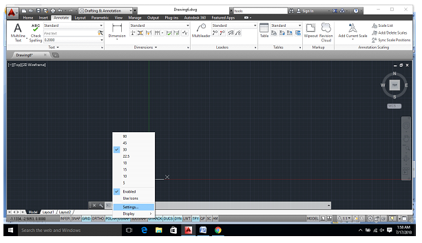
  • Then go to polar settings
  • In the opened dialogue box select “POLAR TRACKING”.
  • Set the increment angle as per your requirement.
(here taken as 30)

  • Select line command(L+enter) and draw a line of required length.

(here taken as 120mm)


  • Now you’ll see that the line can’t be drawn further in right direction, so we need to change the plane for it.
  • The plane can be changed by using function key “F5”. And the line can be drawn easily.
  • Now draw as shown in the figure above, by changing the plane of the cursor accordingly.
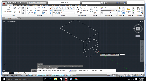
  • Now select the ellipse tool above or type command “EL+enter”.


  • Now, select isocircle in the command box.


  • Select the mid-point of the line as shown in the figure.
  • And start drawing an isocircle.


  • Change the plane using the function key “F5”, if required.

  • Create an isocircle of required radius.
(here taken as 40)

  • Copy the lines as shown in the figure taking required distance
(here taken as 20mm)

  • Trim the unrequired lines using the trim command.
  • Type “TR+enter” in the command box for using the trim tool.

  • Use quadrant tool in line command to join the rounded curves.


  • Trim the unrequired lines which are not required in the drawing.


  • Find the center-point of the rectangle as shown in the figure.
  • For center point- right click on the midpoint of one side and drag to the mid-point of any other side of rectangle and then drag to center.


  • Again, draw an isocircle of required radius.
(here taken as 40)


  • Copy the isocircle at a distance of 15mm above it.


  • Again, connect the curves using quadrant tool in line command.


  • Now taking the center point draw another isocircle of the required radius.
(here taken as 30)


  • Copy the isocircle of radius 30mm, 15mm below it in the same plane
  • Taking it as a centre again draw an isocircle of required radius
(here taken as 15mm)


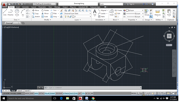
  • Trim the unrequired lines and finally, we are completed with our isometric drawing.

NOW FOR DIMENSIONS


  • Select “ALIGNED” option for marking dimensions of an isometric drawing.


  • Select start and endpoint of the required line and extend it as per requirement as shown below.


  • Similarly, mark all other required points as shown above. 


  • Now, for marking the dimensions of isocircle, select leader from the toolbar.


  • Select the isocircle and extend the line as per the requirement.
  • And then enter the radius of the isocircle.


  • Similarly, do for all other required isocircles for marking their radius.
  • As we can see the dimensions are not visible as their size is too small.
  • So, we have to adjust their size as required.


  • Select “ANNOTATE” in the toolbar.
  • Select the standard setting option as shown above in the figure.


  • Select “MODIFY”, in the dialogue box.


  • Go to “FIT”, and enter the required size of the text.
(here it was set to 18)


  • Now, we can see that the dimensions are clearly visible.

  • Similarly, for radius markings.
  • Select “MULTILEADER” settings and select “MODIFY” option.
  • Go to “LEADER STRUCTURE” and enter the required text size.
(here it was set to 18)


  • Now, as we can see all the dimensions are now clearly visible.


  • To align the dimensions marking, select “ANNOTATE”
  • Then go to “DIMENSIONS” and select “OBLIQUE”. 
  • Select the required dimensions which are to be done.


  • Enter the angle of inclination as per the requirement.
(here it was 30, 120 and 150 respectively) 


  • .You have successfully added dimensions to your isometric drawing.
So, this is how we design an isometric drawing in AutoCAD. Hope my efforts will help you to comprehend AutoCAD better. But I would highly recommend you to go for a training institute as for becoming an AutoCAD Master you need professional training and right guidance. One such professional and renowned training institute is ADMEC Multimedia Institute where you will get industry standard and relevant training on latest applications such as AutoCAD, 3DS Max, Revit, Google SketchUp etc.
Author Section: Hi, I’m Priyam Narang, a student of ADMEC and has successfully completed my AutoCAD Master course  I hope this blog would be beneficial to you. 

To read more such blogs on architecture interior designing, you can go through All CAD Blogs 

Featured Post

ADMEC Multimedia Institute Scholarship Program

The ADMEC Multimedia Institute scholarship program aims to select and trained talented non working female, married woman and non married m...