
If we talk about the isometric drawing in AutoCAD then these drawing aren’t 3d drawing. We can’t compare them with 3d. If you want to learn advanced AutoCAD then comprehending the concepts of isometric drawing is really significant.
In this article, I will explain the methods of creating an isometric drawing in AutoCAD. So, let’s start from the exact meaning of Isometric drawings.
ISOMETRIC DRAWING – Un Insight
- If we talk Isometric Drawing then it is basically related or we can say similar to PERSPECTIVE DRAWING, which is widely used by architecture designers to present 3D forms on a 2D drawing plane.
- Isometric drawing has the same functions like the perspective drawings, they have a little difference in their applications: -
- Perspective drawing tracks the small size of objects as they recede from view. Drawings like Isometric have the same sizes and this is the reason why these drawings track all objects of equal dimensions.
- If we talk about Perspective drawings, they show alterations in the object’s shape and angle to the form they recommend. Through this way, the architect designer exhibits depth in the drawing. Whereas this is not similar to isometric drawings as these drawings have static shapes and angles.
Now I’ll explain how to draw an isometric drawing step-by-step in AutoCAD by making a sample drawing as given below.

- For making an isometric drawing, first of all, enter a command “SNAPSTYL”.
- And then enter an initial value for ”SNAPSTYL” as…‘1’.

- An isometric selection cursor will appear on the screen.
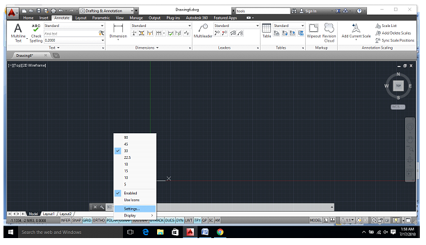
- Then make sure that polar in “ON”
- Then go to polar settings

- In the opened dialogue box select “POLAR TRACKING”.
- Set the increment angle as per your requirement.
(here taken as 30)

- Select line command(L+enter) and draw a line of required length.
(here taken as 120mm)

- Now you’ll see that the line can’t be drawn further in right direction, so we need to change the plane for it.
- The plane can be changed by using function key “F5”. And the line can be drawn easily.

- Now draw as shown in the figure above, by changing the plane of the cursor accordingly.

- Now select the ellipse tool above or type command “EL+enter”.

- Now, select isocircle in the command box.

- Select the mid-point of the line as shown in the figure.
- And start drawing an isocircle.

- Change the plane using the function key “F5”, if required.
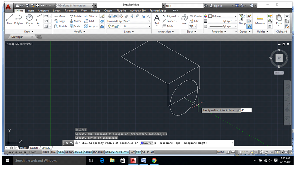
- Create an isocircle of required radius.
(here taken as 40)

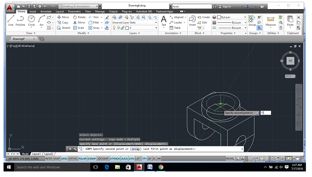
- Copy the lines as shown in the figure taking required distance
(here taken as 20mm)

- Trim the unrequired lines using the trim command.
- Type “TR+enter” in the command box for using the trim tool.

- Use quadrant tool in line command to join the rounded curves.

- Trim the unrequired lines which are not required in the drawing.

- Find the center-point of the rectangle as shown in the figure.
- For center point- right click on the midpoint of one side and drag to the mid-point of any other side of rectangle and then drag to center.

- Again, draw an isocircle of required radius.
(here taken as 40)

- Copy the isocircle at a distance of 15mm above it.

- Again, connect the curves using quadrant tool in line command.

- Now taking the center point draw another isocircle of the required radius.
(here taken as 30)
- Copy the isocircle of radius 30mm, 15mm below it in the same plane

- Taking it as a centre again draw an isocircle of required radius
(here taken as 15mm)

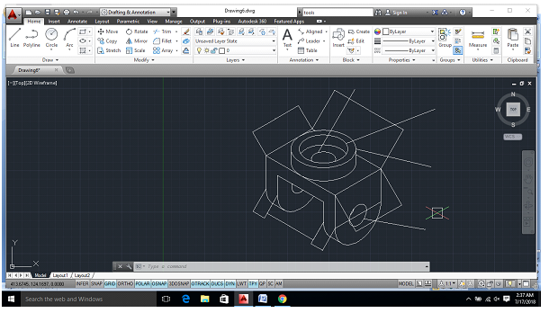
- Trim the unrequired lines and finally, we are completed with our isometric drawing.
NOW FOR DIMENSIONS

- Select “ALIGNED” option for marking dimensions of an isometric drawing.

- Select start and endpoint of the required line and extend it as per requirement as shown below.


- Similarly, mark all other required points as shown above.

- Now, for marking the dimensions of isocircle, select leader from the toolbar.

- Select the isocircle and extend the line as per the requirement.
- And then enter the radius of the isocircle.
- Similarly, do for all other required isocircles for marking their radius.

- As we can see the dimensions are not visible as their size is too small.
- So, we have to adjust their size as required.

- Select “ANNOTATE” in the toolbar.
- Select the standard setting option as shown above in the figure.

- Select “MODIFY”, in the dialogue box.

- Go to “FIT”, and enter the required size of the text.
(here it was set to 18)

- Now, we can see that the dimensions are clearly visible.

- Similarly, for radius markings.
- Select “MULTILEADER” settings and select “MODIFY” option.

- Go to “LEADER STRUCTURE” and enter the required text size.
(here it was set to 18)

- Now, as we can see all the dimensions are now clearly visible.

- To align the dimensions marking, select “ANNOTATE”
- Then go to “DIMENSIONS” and select “OBLIQUE”.

- Select the required dimensions which are to be done.

- Enter the angle of inclination as per the requirement.
(here it was 30, 120 and 150 respectively)

- .You have successfully added dimensions to your isometric drawing.
So, this is how we design an isometric drawing in AutoCAD. Hope my efforts will help you to comprehend AutoCAD better. But I would highly recommend you to go for a training institute as for becoming an AutoCAD Master you need professional training and right guidance. One such professional and renowned training institute is ADMEC Multimedia Institute where you will get industry standard and relevant training on latest applications such as AutoCAD, 3DS Max, Revit, Google SketchUp etc.
Author Section: Hi, I’m Priyam Narang, a student of ADMEC and has successfully completed my AutoCAD Master course I hope this blog would be beneficial to you.
To read more such blogs on architecture interior designing, you can go through All CAD Blogs


No comments:
Post a Comment